東京大学 情報理工学系研究科 電子情報学専攻 2017年度 専門 第2問
Author
Description
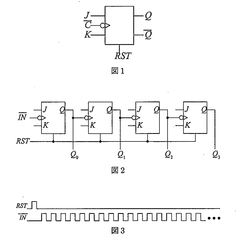
Let us consider a falling-edge-triggered JK flip-flop as shown in Fig.1. This JK flip-flop is reset to \((Q,\overline{Q}) = (0,1)\) when \(RST = 1\). Answer the following questions.
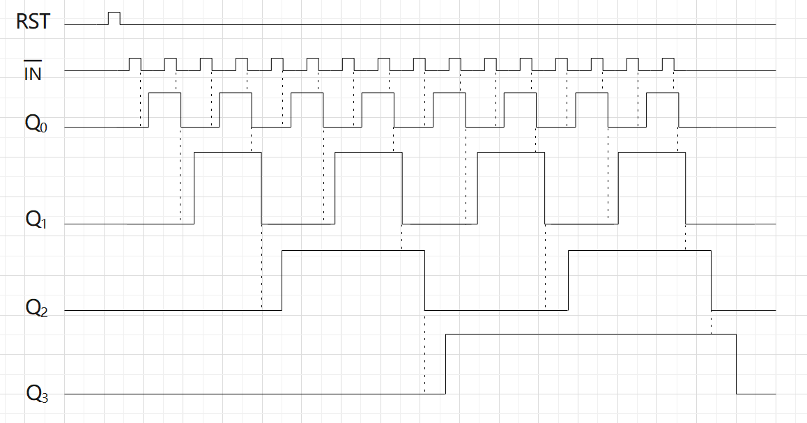
(1) Let us assume a 4-bit counter as shown in Fig.2, and the input signals shown in Fig.3 are given to the counter. Show a time chart of the outputs \(Q_0-Q_3\). Here, let us assume that all the \(J\) and \(K\) terminals are connected to 1, and the delay of each JK flip-flop, \(\tau\) , cannot be neglected.
(2) Modify the circuit in Fig.2 so that the outputs \(Q_0-Q_3\) change simultaneously, and show its schematic. (Such a circuit is called a parallel counter or a synchronous counter.)
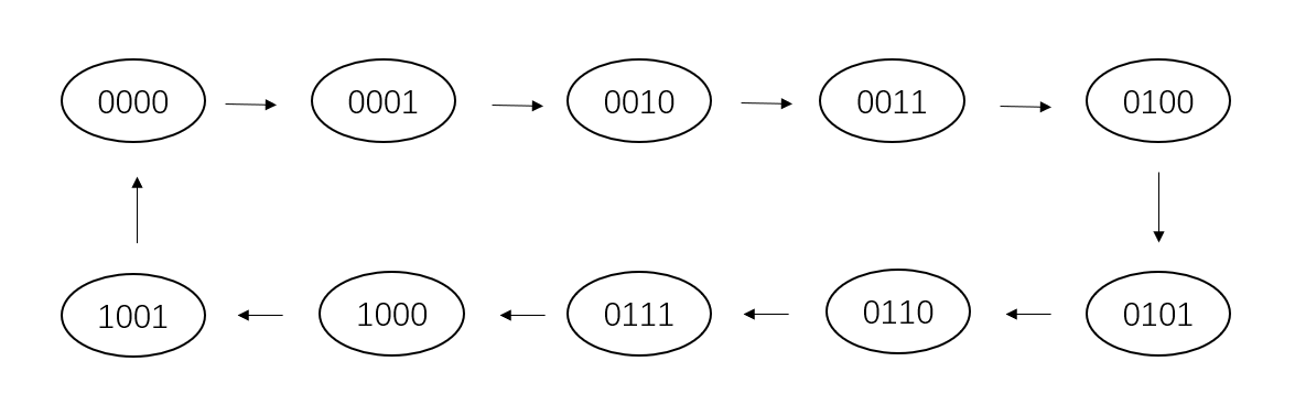
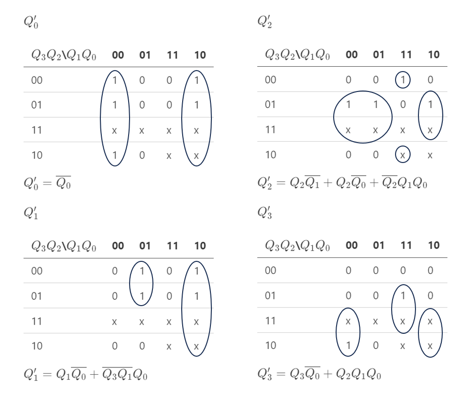
(3) Let us design a parallel decimal counter. A decimal counter is a circuit that starts counting from (\(Q_3Q_2Q_1Q_0\)) = (0000) up to (\(Q_3Q_2Q_1Q_0\)) = (1001) and then returns to (\(Q_3Q_2Q_1Q_0\)) = (0000) in the next state. Show a state transition diagram and a Karnaugh map of the counter.
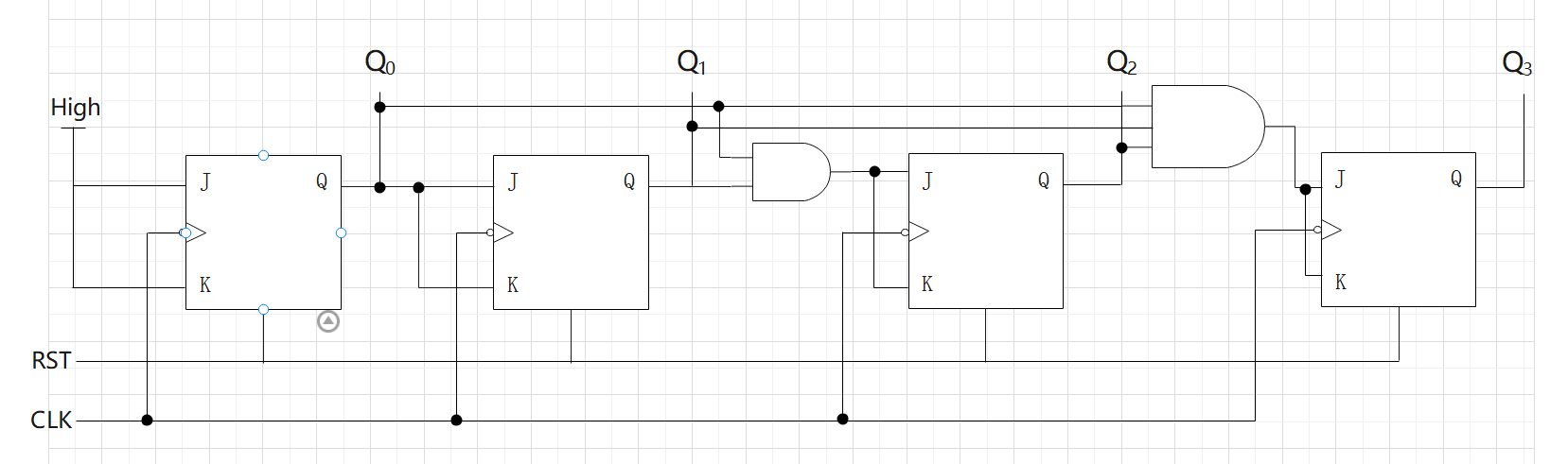
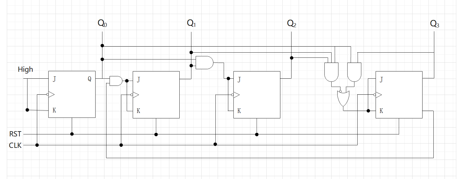
(4) Show a schematic of a parallel decimal counter by using the results in (3).
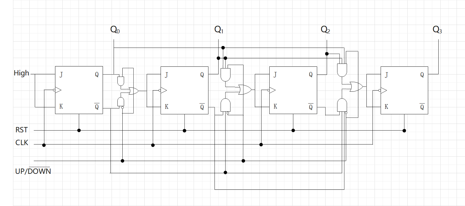
(5) Modify the circuit in (2) to an up/down counter and show its schematic. An up/down counter is a counter whose operation mode can be changed either to count-up or count-down by a control signal \(UP/\overline{DOWN}\).
Kai
(1)
(2)
(3)
| \(Q_3\) | \(Q_2\) | \(Q_1\) | \(Q_0\) | \(Q_3'\) | \(Q_2'\) | \(Q_1'\) | \(Q_0'\) |
|---|---|---|---|---|---|---|---|
| 0 | 0 | 0 | 0 | 0 | 0 | 0 | 1 |
| 0 | 0 | 0 | 1 | 0 | 0 | 1 | 0 |
| 0 | 0 | 1 | 0 | 0 | 0 | 1 | 1 |
| 0 | 0 | 1 | 1 | 0 | 1 | 0 | 0 |
| 0 | 1 | 0 | 0 | 0 | 1 | 0 | 1 |
| 0 | 1 | 0 | 1 | 0 | 1 | 1 | 0 |
| 0 | 1 | 1 | 0 | 0 | 1 | 1 | 1 |
| 0 | 1 | 1 | 1 | 1 | 0 | 0 | 0 |
| 1 | 0 | 0 | 0 | 1 | 0 | 0 | 1 |
| 1 | 0 | 0 | 1 | 0 | 0 | 0 | 0 |
(4)
(5)