東京大学 工学系研究科 機械工学専攻 機械工学第2部 2026年9月実施 問題 3
Author
Description
全問に解答すること.日本語または英語で解答すること.
図 3-1 および図 3-2 に,金属の切削加工における切削工具の刃先近傍を単純化した模式図を示す.図 3-1 は切削工具に働く力,図 3-2 は切りくずにおける力のつり合いにそれぞれ注目した同一の加工を表している.これらの模式図で表される切削加工において,切削工具の刃先角やすくい面の摩擦係数に関する設計指針を考える.図中の切削工具は静止している工作物に一定の切り込み深さ で切り込みながら,一定の速度 で移動しており,切りくずを生成しながら工作物を削っている.工作物は紙面に垂直な方向に幅 を有しており,幅方向には現象が一様であるとする.図 3-1 に示されている は合力としての切削力であり,切削力はすくい面を介してのみ切削工具に作用するものと考える. はすくい角, は摩擦角をそれぞれ表している.以下の設問に答えよ.
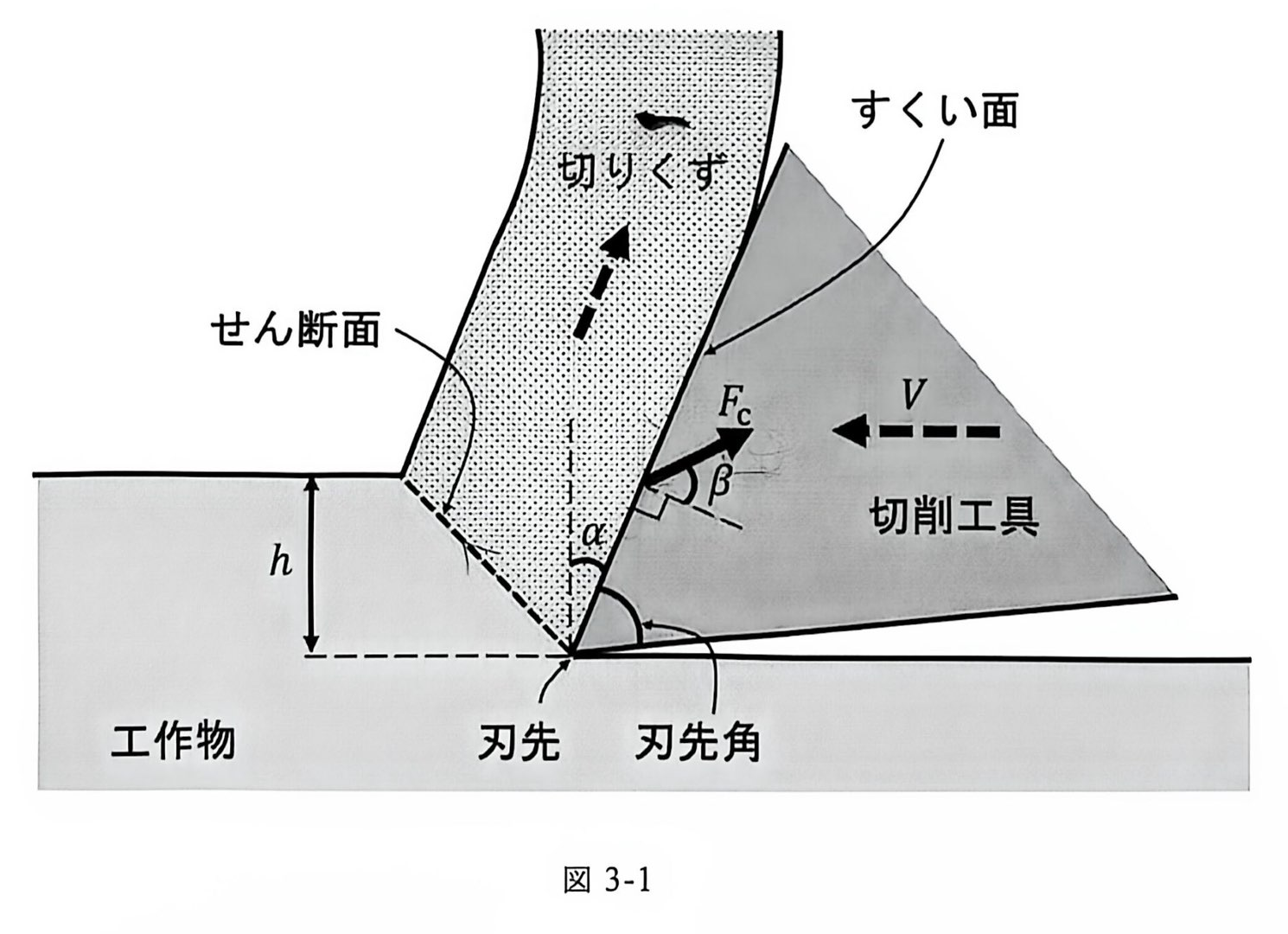
(1) 切削工具のすくい面と切りくずの間の摩擦係数を とした場合, と の間の関係を示せ.
次に,図 3-2 に示されているように切りくずに注目する.切りくずは,せん断角 で特徴づけられるせん断面における連続的なせん断変形により生成される.刃先近傍の切りくずには 2 種類の力が働いている.一つは切削工具のすくい面から働く力,もう一つはせん断面から働く力である.切りくずは同じ形状で定常的に生成され,切りくずに働く力は釣り合っているものとする.ただし,せん断面にはせん断応力 が一様に生じているものとする.せん断応力 は材料の特性のみから決まり,加工条件には依存しないものとする.以下の設問に答えよ.
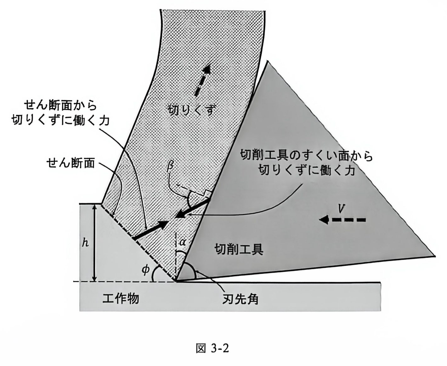
(2) せん断面から切りくずに働く力の,せん断面に沿った方向の成分 を ,,, を用いて表せ.
(3) が以下の式で表されることを示せ.
式 (3-1) で表される には が含まれている.一般に,せん断角 を正確に求めることは難しいが,式 (3-2) のように推定できることが知られている.
式 (3-2) を用いて以下の設問に答えよ.
(4) 切削力 および切削動力 (切削工具が単位時間あたりになす仕事)を,, の関数としてそれぞれ表せ.ただし,必要に応じて以下に示す三角関数の公式を用いてもよい.
(5) 切削力,切削動力および刃先強度の視点から,切削工具の刃先角およびすくい面における摩擦係数をどのように設定したら良いか,設問 (4) の結果を用いて設計指針を述べよ.
English
Answer all questions in Japanese or English.
Problem 3
Figure 3-1 and Figure 3-2 show simplified schematic diagrams of a cutting edge region during cutting of a metallic workpiece. Both figures represent the same cutting process, where Figure 3-1 focuses on the force exerted on the cutting tool while Figure 3-2 focuses on the force balance in the chip region. Consider the design guidelines of the cutting tool regarding wedge angle and friction coefficient on the rake face for the cutting process that is shown in the figures. The cutting tool in the figures moves at a constant velocity while cutting into the stationary workpiece at a constant depth of cut , removing material from it while generating chips. The workpiece has a width of in the perpendicular direction to this paper and it is assumed that the material removal phenomenon is uniform in that direction. which is indicated in Figure 3-1 is the cutting force as a combined force and it acts on the cutting tool only through its rake face. is the rake angle, and is the friction angle. Answer the following questions.
(1) When the friction coefficient between the rake face of the cutting tool and the chip is denoted as , derive the relation between and .
Next, we focus on the chip as described in Figure 3-2. The chip is continuously generated by the shear deformation on the shear plane which is characterized by the shear angle . Two forces are exerted on the chip near the cutting edge. One is the force from the rake face of the cutting tool, the other is the force from the shear plane. The chip is assumed to be continuously generated in the same shape and the forces acting on the chip are also balanced. The shear stress acting on the shear plane is assumed to be uniformly distributed in the shear plane. It is also assumed to depend solely on the workpiece material and does not depend on the cutting conditions. Answer the following questions.
(2) Express which is the force component parallel to the shear plane of the force acting on the chip from the shear plane by using , , and .
(3) Show that is expressed as given below.
represented by Equation (3-1) includes which is generally difficult to obtain accurately. However, it is known that can be estimated as shown in Equation (3-2).
Answer the following questions by utilizing Equation (3-2).
(4) Express the cutting force and the cutting power which is the work done by the cutting tool per unit time as functions of and . You may use the following trigonometric formula if needed.
(5) From the perspectives of cutting force, cutting power, and cutting edge strength, describe the design guidelines utilizing the result of Question (4) for how the wedge angle of a cutting tool and the friction coefficient on the rake face should be decided.
题目描述
请回答全部问题。请用日语或英语作答。
图 3-1 和图 3-2 是金属切削加工中刀刃附近的简化示意图。两图表示同一切削过程:图 3-1 关注作用在切削刀具上的力,图 3-2 关注切屑中的力平衡。针对图示切削过程,考虑刀具楔角以及前刀面摩擦系数的设计准则。图中的切削刀具以恒定切削深度 切入静止工件,并以恒定速度 移动,在产生切屑的同时切除工件材料。工件在垂直纸面方向上的宽度为 ,假设沿宽度方向的现象均匀。图 3-1 中的 为作为合力的切削力,假定切削力仅通过前刀面作用在切削刀具上。 和 分别表示前角与摩擦角。回答以下问题。
(1) 若切削刀具前刀面与切屑之间的摩擦系数为 ,给出 与 之间的关系。
接下来,如图 3-2 所示,考察切屑。切屑由剪切面上的连续剪切变形形成,该剪切面以剪切角 表征。刀刃附近的切屑受到两种力:一种来自刀具的前刀面,另一种来自剪切面。假设切屑以相同形状稳定生成,且作用在切屑上的力保持平衡。剪切面上均匀作用有剪应力 ,它仅由材料特性决定,与加工条件无关。回答以下问题。
(2) 剪切面作用于切屑的力沿剪切面方向的分量记为 ,用 、、 和 表示 。
(3) 证明 可由下式表示。
式 (3-1) 中的 含有 。一般而言,准确求得剪切角 很困难,但已知可以用式 (3-2) 估计。
利用式 (3-2) 回答以下问题。
(4) 分别将切削力 和切削功率 (切削刀具在单位时间内所做的功)表示为 和 的函数。必要时可使用下列三角恒等式。
(5) 从切削力、切削功率及刀刃强度的角度,利用第 (4) 问的结果,说明应如何选择刀具的楔角及前刀面的摩擦系数,并给出设计准则。
Kai
(1)
すくい面の法線力の大きさを ,摩擦力の大きさを とする。摩擦角の定義から ,摩擦係数の定義から なので,
(2)
切りくずに働く二つの力はつり合うので,せん断面からの合力の大きさも である。図の右向きを 軸,上向きを 軸とすれば,この力は
せん断面に沿う右下向きの単位ベクトル に射影して,
(3)
せん断面の断面内の長さは ,幅は なので,その面積は である。せん断応力が一様であることから,
設問 (2) の結果と合わせれば,
(4)
とおく。与えられた式 (3-2) より であるから,
したがって,
工具は左向きに速さ で動くため,必要な切削動力は,抵抗力の速度方向成分の大きさと の積である。 は合力なので,
よって
(5)
に対応する の範囲で,
したがって, を小さくすれば,切削力と切削動力をともに低減できる。摩擦係数 を小さくすると摩擦角 が小さくなるので,すくい面の摩擦係数は小さい方がよい。
また,すくい角 を大きくすると切削力と切削動力は小さくなる。ただし,逃げ角を一定とすれば,すくい角の増大は刃先角の減少に対応し,刃先が薄くなるため刃先強度が低下する。したがって,必要な刃先強度を確保できる範囲で刃先角を小さくし,すくい面の摩擦を低減するように設計する。刃先強度の条件が与えられていないため,最適な刃先角の数値までは決定できない。
Reference
- 東京大学 2027 年度大学院修士課程入学試験(2026 年 9 月 1 日実施),機械工学第 2 部・問題 3。投稿者提供の原題スキャン:日本語 1 ページ,日本語 2 ページ,日本語 3 ページ。
- 英語版原題スキャン:1 ページ,2 ページ,3 ページ。
- 試験表紙。原題・原図の権利は東京大学に帰属する。
- cdc95-04 の参考解答(PR #151)。
- 三菱マテリアル:Tool geometry(すくい角と刃先強度)。