東京大学 情報理工学系研究科 電子情報学専攻 2026年1月実施 専門 第2問
Author
Description
Recalled statement. A synchronous circuit has a one-bit input and a one-bit output . The output is exactly when the previous sampled input was and the current input is . Before the first input has been sampled, the output is for either value of .
(1) Draw the state transition diagram.
(2) Draw the state transition table.
(3) Express the next-state bits and output using the current state bits and input . Use Karnaugh maps to simplify the expressions.
(4) Draw an implementation using AND, OR, NOT gates and D flip-flops.
题目描述
同步电路有一位输入 和一位输出 。前一次采样为 、当前输入为 时输出 ,其余情况输出 。尚未采样任何输入时,无论 为何,输出均为 。求状态图、状态表、由卡诺图化简的次态及输出表达式,并用指定逻辑门和 D 触发器实现。
Kai
The following (1)–(4) use a combinational Mealy output. A clocked Moore-output implementation is given afterward.
(1)
Use a Mealy machine. State means that the previous input was ; state means that it was . The initial state can also be , because its output is for both possible first inputs. Edge labels are input/output.
(2)
Encode by and by .
| 0 | 0 | 0 | 0 |
| 0 | 1 | 1 | 1 |
| 1 | 0 | 0 | 0 |
| 1 | 1 | 1 | 0 |
(3)
The Karnaugh maps are
| : / | 0 | 1 |
|---|---|---|
| 0 | 0 | 1 |
| 1 | 0 | 1 |
| : / | 0 | 1 |
|---|---|---|
| 0 | 0 | 1 |
| 1 | 0 | 0 |
Grouping the two cells of the first map gives
(4)
Connect to the D input, and combine with the complemented Q output in an AND gate. Initialize Q to before sampling starts. The output is evaluated from the current input and the state holding the previous sample; the active clock edge stores the current sample.
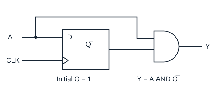
Clocked state-output interpretation
If must remain at the detected value after the sampling edge, use a three-state Moore machine. Let mean “last input , output ”, mean “last input , output ”, and mean “last input , output ”. Start in , whose initial output is .
Encode , , in bits . The state transition table is:
| State | Next state for | Next state for | |
|---|---|---|---|
| 0 | 00 | 01 | |
| 1 | 00 | 10 | |
| 0 | 00 | 10 |
The Karnaugh maps, with unused state as a don't-care, are:
| : / | 0 | 1 |
|---|---|---|
| 00 | 0 | 0 |
| 01 | 0 | 1 |
| 11 | ||
| 10 | 0 | 1 |
| : / | 0 | 1 |
|---|---|---|
| 00 | 0 | 1 |
| 01 | 0 | 0 |
| 11 | ||
| 10 | 0 | 0 |
| : / | 0 | 1 |
|---|---|---|
| 0 | 0 | 1 |
| 1 | 0 |
Thus, with the shared term ,
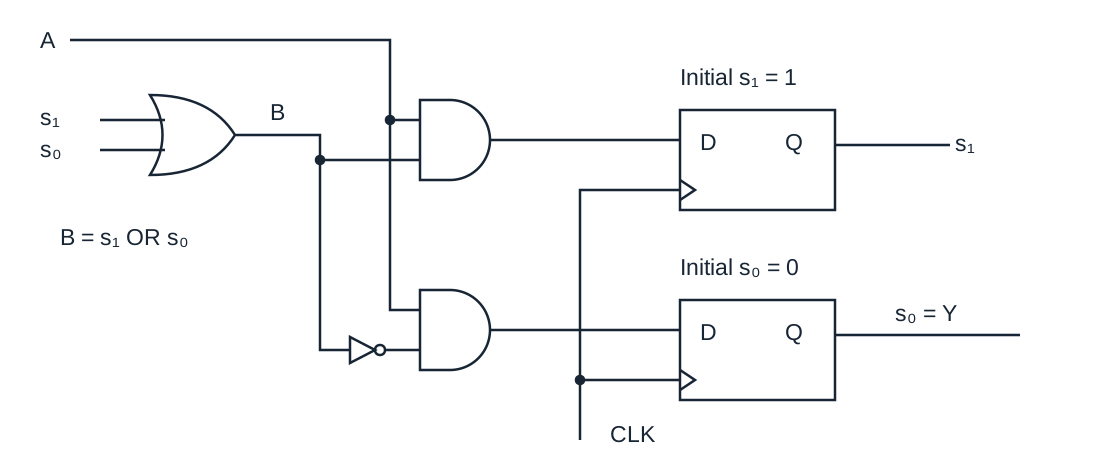
The two D flip-flops use the same clock and start at . The labelled nets connect each register output to the OR inputs.