東京大学 情報理工学系研究科 コンピュータ科学専攻 2016年2月実施 問題4
Author
Description
The majority gate is a binary logic gate defined as follows: has inputs and output. The output is if two or three of the inputs are 1; and 0 otherwise.
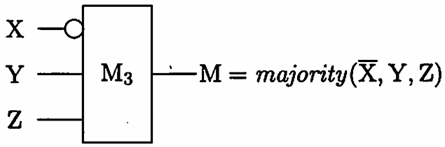
When you answer circuit designs in the questions below, you can use NOT gates and constants and in addition to gates, but other gates such as AND or OR cannot be used. You should draw an gate as a rectangle labeled with , and a NOT gate as a circle, as shown in the following example:
Answer the following questions. Try to make -levels (i.e. the maximum number of serially connected gates) as small as possible in your answers.
(1) Design and depict the following logic circuits:
- (a) AND of inputs,
- (b) OR of inputs,
- () XOR of inputs.
(2) A 1-bit full adder is defined as follows: has inputs and outputs called (sum) and (carry), respectively. and are defined so that is equal to the sum of the input bits.
Design and depict a -bit full adder . Answer its -level, too. You can use the circuits you have designed in Question (1).
(3) Design and depict a -bit full adder . Answer its -level, too.
Here takes, as inputs: (i) two unsigned -bit integers, and (ii) a carry bit.
It outputs the -bit sum. You can use the circuits you have designed in Questions (1) and (2).
(4) Design and depict a -bit multiplier . Answer its -level, too.
Here takes two unsigned -bit integers as inputs. It outputs the -bit product of the inputs. You can use the circuits you have designed in Questions (1), (2), and (3).
题目描述
三输入多数门 有三个输入和一个输出:三个输入中至少有两个为 时输出 ,否则输出 。
以下各题设计电路时,除 外只可使用非门和常量 ,不得使用与门、或门等其他门。绘图时按题中示例,用标有 的矩形表示多数门,用圆形表示非门。回答时应尽量减小 层数,即任一通路上串联的 门的最大数量。
(1)设计并画出以下逻辑电路:
- 两输入与;
- 两输入或;
- 两输入异或。
(2)一位全加器 有三个输入以及和位 、进位 两个输出,且要求 等于三个输入位之和。设计并画出 ,同时给出其 层数。可以使用第(1)问设计的电路。
(3)设计并画出四位全加器 ,并给出其 层数。该电路输入两个无符号四位整数和一个进位位,输出五位和;可以使用第(1)、(2)问的电路。
(4)设计并画出四位乘法器 ,并给出其 层数。该电路输入两个无符号四位整数,输出八位乘积;可以使用前面各问设计的电路。
考点
- 多数门逻辑综合:用多数门、非门和常量实现与、或、异或等基本布尔函数。
- 全加器与关键路径:组合一位及四位全加器,并按串联多数门数计算逻辑层深。
- 组合二进制乘法器:生成部分积并用加法器网络求和,在功能正确的同时分析多数门层数。
Kai
(1)
- OR() =
- AND() =
- XOR() = AND( OR(), NOT( AND() ) =
XOR is "--level".
(2)
Classic -bit full adder. Just draw a table and then depict the circuit. Let be inputs.
yields - level (2x XOR).
yields - level (OR with 2-level AND).
Thus, has - level.
Bonus: . Thanks Igor!
(3)
Connect in series. It's level is .
(4)
Classic -bit multiplier (google for images). Connect three -bit adders in series and try not to get messed with connections. level is: : each of three has level and there's one level of AND gates preceding 's.