東京大学 情報理工学系研究科 創造情報学専攻 2006年8月実施 筆記試験 第3問 Author itsuitsuki
Description 出典:大学公式問題冊子の保存版 。
日本語
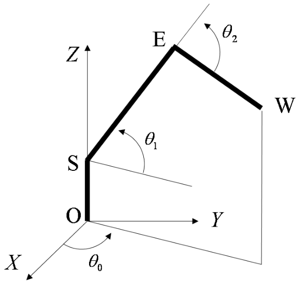
図 1 1 1 3 3 3 O , S , E \mathrm{O, S, E} O , S , E 3 3 3 O \mathrm{O} O X Y Z XYZ X Y Z Z Z Z S , E \mathrm{S, E} S , E O S E W \mathrm{OSEW} OSEW O S ‾ = l 0 , S E ‾ = l 1 , E W ‾ = l 2 \overline{\mathrm{OS}}=l_0, \overline{\mathrm{SE}}=l_1, \overline{\mathrm{EW}}=l_2 OS = l 0 , SE = l 1 , EW = l 2
(1) 点 W \mathrm{W} W W ⃗ ( w x , w y , w z ) \vec{W}(w_x, w_y, w_z) W ( w x , w y , w z ) 3 3 3 O , S , E \mathrm{O, S, E} O , S , E θ ⃗ ( θ 0 , θ 1 , θ 2 ) \vec{\theta}(\theta_0, \theta_1, \theta_2) θ ( θ 0 , θ 1 , θ 2 ) W ⃗ = f ( θ ⃗ ) \vec{W}=f(\vec{\theta}) W = f ( θ )
(2) 点 W \mathrm{W} W V ⃗ ( w ˙ x , w ˙ y , w ˙ z ) \vec{V}(\dot{w}_x, \dot{w}_y, \dot{w}_z) V ( w ˙ x , w ˙ y , w ˙ z ) 3 3 3 O , S , E \mathrm{O, S, E} O , S , E Ω ⃗ ( θ ˙ 0 , θ ˙ 1 , θ ˙ 2 ) \vec{\Omega}(\dot{\theta}_0, \dot{\theta}_1, \dot{\theta}_2) Ω ( θ ˙ 0 , θ ˙ 1 , θ ˙ 2 )
(3) 逆運動学計算式 θ ⃗ = f − 1 ( W ⃗ ) \vec{\theta}=f^{-1}(\vec{W}) θ = f − 1 ( W )
(4) アームの先端 W \mathrm{W} W F ⃗ ( F x , F y , F z ) \vec{F}(F_x, F_y, F_z) F ( F x , F y , F z ) 3 3 3 O , S , E \mathrm{O, S, E} O , S , E τ ⃗ ( τ 0 , τ 1 , τ 2 ) \vec{\tau}(\tau_0, \tau_1, \tau_2) τ ( τ 0 , τ 1 , τ 2 )
English
Figure 1 shows an arm which has three joints at O, S and E. The axis of the joint O rotates around Z Z Z X Y Z XYZ X Y Z O S ‾ = l 0 , S E ‾ = l 1 , E W ‾ = l 2 \overline{OS}=l_0, \overline{SE}=l_1, \overline{EW}=l_2 OS = l 0 , SE = l 1 , E W = l 2
(1) Show the equation of the forward kinematics of the arm W ⃗ = f ( θ ⃗ ) \vec{W}=f(\vec{\theta}) W = f ( θ ) W ⃗ ( w x , w y , w z ) \vec{W}(w_x,w_y,w_z) W ( w x , w y , w z ) θ ⃗ ( θ 0 , θ 1 , θ 2 ) \vec{\theta}(\theta_0,\theta_1,\theta_2) θ ( θ 0 , θ 1 , θ 2 )
(2) Describe the velocity V ⃗ ( w ˙ x , w ˙ y , w ˙ z ) \vec{V}(\dot{w}_x,\dot{w}_y,\dot{w}_z) V ( w ˙ x , w ˙ y , w ˙ z ) Ω ⃗ ( θ ˙ 0 , θ ˙ 1 , θ ˙ 2 ) \vec{\Omega}(\dot{\theta}_0,\dot{\theta}_1,\dot{\theta}_2) Ω ( θ ˙ 0 , θ ˙ 1 , θ ˙ 2 )
(3) Show the equation of the inverse kinematics of the arm θ ⃗ = f − 1 ( W ⃗ ) \vec{\theta}=f^{-1}(\vec{W}) θ = f − 1 ( W )
(4) Assume a force F ⃗ ( F x , F y , F z ) \vec{F}(F_x,F_y,F_z) F ( F x , F y , F z ) τ ⃗ ( τ 0 , τ 1 , τ 2 ) \vec{\tau}(\tau_0,\tau_1,\tau_2) τ ( τ 0 , τ 1 , τ 2 )
题目描述
如图 1,有一条在 O , S , E O,S,E O , S , E O O O X Y Z XYZ X Y Z Z Z Z S , E S,E S , E O S E W OSEW OSE W
O S ‾ = l 0 , S E ‾ = l 1 , E W ‾ = l 2 . \overline{OS}=l_0,\qquad \overline{SE}=l_1,\qquad \overline{EW}=l_2. OS = l 0 , SE = l 1 , E W = l 2 . 回答下列问题。
令末端点 W W W W ⃗ = ( w x , w y , w z ) \vec W=(w_x,w_y,w_z) W = ( w x , w y , w z ) O , S , E O,S,E O , S , E θ ⃗ = ( θ 0 , θ 1 , θ 2 ) \vec\theta=(\theta_0,\theta_1,\theta_2) θ = ( θ 0 , θ 1 , θ 2 ) W ⃗ = f ( θ ⃗ ) \vec W=f(\vec\theta) W = f ( θ )
用三个关节的角速度向量 Ω ⃗ = ( θ ˙ 0 , θ ˙ 1 , θ ˙ 2 ) \vec\Omega=(\dot\theta_0,\dot\theta_1,\dot\theta_2) Ω = ( θ ˙ 0 , θ ˙ 1 , θ ˙ 2 ) W W W V ⃗ = ( w ˙ x , w ˙ y , w ˙ z ) \vec V=(\dot w_x,\dot w_y,\dot w_z) V = ( w ˙ x , w ˙ y , w ˙ z )
求逆运动学公式 θ ⃗ = f − 1 ( W ⃗ ) \vec\theta=f^{-1}(\vec W) θ = f − 1 ( W )
若末端 W W W F ⃗ = ( F x , F y , F z ) \vec F=(F_x,F_y,F_z) F = ( F x , F y , F z ) τ ⃗ = ( τ 0 , τ 1 , τ 2 ) \vec\tau=(\tau_0,\tau_1,\tau_2) τ = ( τ 0 , τ 1 , τ 2 )
题目所用机械臂几何结构沿用原文图 1。
Kai 図の向きに従い、θ 0 \theta_0 θ 0 X X X θ 1 \theta_1 θ 1 S E SE SE θ 2 \theta_2 θ 2 E W EW E W S E SE SE E W EW E W θ 1 − θ 2 \theta_1-\theta_2 θ 1 − θ 2 l 1 , l 2 > 0 l_1,l_2>0 l 1 , l 2 > 0
(1)
ϕ = θ 1 − θ 2 , r = l 1 cos θ 1 + l 2 cos ϕ , h = l 1 sin θ 1 + l 2 sin ϕ \phi=\theta_1-\theta_2,\qquad
r=l_1\cos\theta_1+l_2\cos\phi,\qquad
h=l_1\sin\theta_1+l_2\sin\phi ϕ = θ 1 − θ 2 , r = l 1 cos θ 1 + l 2 cos ϕ , h = l 1 sin θ 1 + l 2 sin ϕ とおけば、各リンクの水平・鉛直成分を加えることにより、
W ⃗ = ( r cos θ 0 r sin θ 0 l 0 + h ) . \boxed{\vec W=
\begin{pmatrix}r\cos\theta_0\\r\sin\theta_0\\l_0+h\end{pmatrix}}. W = r cos θ 0 r sin θ 0 l 0 + h . r r r
(2)
(1)を時間微分すると V ⃗ = J Ω ⃗ \vec V=J\vec\Omega V = J Ω
J = ∂ W ⃗ ∂ θ ⃗ = ( − r sin θ 0 − h cos θ 0 l 2 sin ϕ cos θ 0 r cos θ 0 − h sin θ 0 l 2 sin ϕ sin θ 0 0 r − l 2 cos ϕ ) . \boxed{J=\frac{\partial\vec W}{\partial\vec\theta}=
\begin{pmatrix}
-r\sin\theta_0&-h\cos\theta_0&l_2\sin\phi\cos\theta_0\\
r\cos\theta_0&-h\sin\theta_0&l_2\sin\phi\sin\theta_0\\
0&r&-l_2\cos\phi
\end{pmatrix}}. J = ∂ θ ∂ W = − r sin θ 0 r cos θ 0 0 − h cos θ 0 − h sin θ 0 r l 2 sin ϕ cos θ 0 l 2 sin ϕ sin θ 0 − l 2 cos ϕ . 例えば第3列の符号は ∂ ϕ / ∂ θ 2 = − 1 \partial\phi/\partial\theta_2=-1 ∂ ϕ / ∂ θ 2 = − 1
(3)
ρ = w x 2 + w y 2 \rho=\sqrt{w_x^2+w_y^2} ρ = w x 2 + w y 2 h = w z − l 0 h=w_z-l_0 h = w z − l 0
D = ρ 2 + h 2 − l 1 2 − l 2 2 2 l 1 l 2 = cos θ 2 . D=\frac{\rho^2+h^2-l_1^2-l_2^2}{2l_1l_2}=\cos\theta_2. D = 2 l 1 l 2 ρ 2 + h 2 − l 1 2 − l 2 2 = cos θ 2 . よって到達可能条件は ∣ D ∣ ≤ 1 |D|\le1 ∣ D ∣ ≤ 1
∣ l 1 − l 2 ∣ ≤ ρ 2 + h 2 ≤ l 1 + l 2 |l_1-l_2|\le\sqrt{\rho^2+h^2}\le l_1+l_2 ∣ l 1 − l 2 ∣ ≤ ρ 2 + h 2 ≤ l 1 + l 2 である。まず ρ > 0 \rho>0 ρ > 0 σ ∈ { 1 , − 1 } \sigma\in\{1,-1\} σ ∈ { 1 , − 1 }
r = σ ρ , θ 0 = atan2 ( w y , w x ) + 1 − σ 2 π r=\sigma\rho,\qquad
\theta_0=\operatorname{atan2}(w_y,w_x)+\frac{1-\sigma}{2}\pi r = σ ρ , θ 0 = atan2 ( w y , w x ) + 2 1 − σ π を選ぶ。さらに肘の2解を
θ 2 = atan2 ( ε 1 − D 2 , D ) , ε ∈ { 1 , − 1 } \boxed{\theta_2=\operatorname{atan2}\!\left(\varepsilon\sqrt{1-D^2},D\right),\quad\varepsilon\in\{1,-1\}} θ 2 = atan2 ( ε 1 − D 2 , D ) , ε ∈ { 1 , − 1 } とし、
θ 1 = atan2 ( h , r ) + atan2 ( l 2 sin θ 2 , l 1 + l 2 cos θ 2 ) \boxed{\theta_1=\operatorname{atan2}(h,r)+
\operatorname{atan2}(l_2\sin\theta_2,l_1+l_2\cos\theta_2)} θ 1 = atan2 ( h , r ) + atan2 ( l 2 sin θ 2 , l 1 + l 2 cos θ 2 ) を得る。これは
r + i h = e i θ 1 ( l 1 + l 2 e − i θ 2 ) r+ih=e^{i\theta_1}(l_1+l_2e^{-i\theta_2}) r + ih = e i θ 1 ( l 1 + l 2 e − i θ 2 ) の偏角を取った式である。角度には 2 π 2\pi 2 π r ≥ 0 r\ge0 r ≥ 0 σ = 1 \sigma=1 σ = 1
ρ = 0 \rho=0 ρ = 0 θ 0 \theta_0 θ 0 r = 0 r=0 r = 0 ρ = h = 0 \rho=h=0 ρ = h = 0 l 1 = l 2 l_1=l_2 l 1 = l 2 θ 2 = π ( m o d 2 π ) \theta_2=\pi\pmod{2\pi} θ 2 = π ( mod 2 π ) θ 1 , θ 0 \theta_1,\theta_0 θ 1 , θ 0 atan2 ( 0 , 0 ) \operatorname{atan2}(0,0) atan2 ( 0 , 0 )
(4)
F ⃗ \vec F F δ θ ⃗ \delta\vec\theta δ θ
τ ⃗ T δ θ ⃗ + F ⃗ T δ W ⃗ = 0 , δ W ⃗ = J δ θ ⃗ \vec\tau^{\mathsf T}\delta\vec\theta+
\vec F^{\mathsf T}\delta\vec W=0,\qquad
\delta\vec W=J\delta\vec\theta τ T δ θ + F T δ W = 0 , δ W = J δ θ なので、保持のためにアクチュエータが与えるトルクは
τ ⃗ = − J T F ⃗ . \boxed{\vec\tau=-J^{\mathsf T}\vec F}. τ = − J T F . F r = F x cos θ 0 + F y sin θ 0 F_r=F_x\cos\theta_0+F_y\sin\theta_0 F r = F x cos θ 0 + F y sin θ 0
τ 0 = r ( F x sin θ 0 − F y cos θ 0 ) , τ 1 = h F r − r F z , τ 2 = − l 2 sin ϕ F r + l 2 cos ϕ F z . \boxed{\begin{aligned}
\tau_0&=r(F_x\sin\theta_0-F_y\cos\theta_0),\\
\tau_1&=hF_r-rF_z,\\
\tau_2&=-l_2\sin\phi\,F_r+l_2\cos\phi\,F_z.
\end{aligned}} τ 0 τ 1 τ 2 = r ( F x sin θ 0 − F y cos θ 0 ) , = h F r − r F z , = − l 2 sin ϕ F r + l 2 cos ϕ F z . なお J T F ⃗ J^{\mathsf T}\vec F J T F