東京大学 情報理工学系研究科 創造情報学専攻 2005年8月実施 筆記試験 第3問
Author
Description
出典:大学公式問題冊子の保存版(日本語版の設問・図を確認)。
日本語
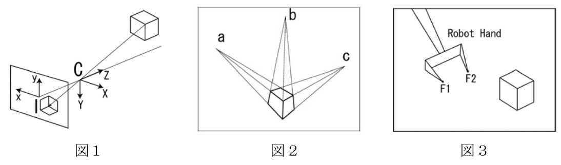
図1に示すように,三次元空間中の物体の光が一点C(光学中心)を通って撮像面に投影されるピンホールカメラを考える.光学中心から撮像面へ垂直に引いた直線は光軸と呼ばれ,撮像面と光軸の交点は画像中心と呼ばれる.図1に示すように,光学中心に三次元のカメラ座標系 C-X,Y,Z をとり,画像中心に二次元の画像座標系 I-x,y をとる.光学中心から撮像面までの距離をfとした場合に,三次元空間の点 の投影面上の点 の座標は次のように表される.
以下の問に答えよ.
(1) 三次元空間中の直線Lの無限遠点が撮像面に投影される点はLの消失点と呼ばれる.点 を通り,方向ベクトル に沿う直線L上の点 の座標を表し,直線Lの消失点の座標 を求めよ.
(2) 図2のように直方体が投影されている画像上で直方体の平行線の消失点 , , の間にはどういう関係式が成立するか示せ.
(3) 直方体が投影されている投影面の映像が濃淡画像として得られるとして,直方体の稜線を濃淡画像の中から得る画像処理について説明せよ.
(4) 図3はロボットの基準座標系で定義される位置と姿勢を指定することでその場所へ動かすことができるロボットハンドの投影像を示す.ロボットハンドの指先F1, F2の投影面上の運動軌跡を画像処理によって得られるとする.直交する3つの方向にロボットハンドを動かして,ロボットの基準座標系からカメラ座標系への変換行列を得る方法を考える.3つの消失点座標に加えて,他にどのような情報が必要となるか説明せよ.
题目描述
考虑图 1 所示的针孔相机:三维空间中物体发出的光经光心 投影到成像平面。过光心且垂直于成像平面的直线称为光轴,光轴与成像平面的交点为图像中心。在光心建立三维相机坐标系 ,在图像中心建立二维图像坐标系 。若光心到成像平面的距离为 ,三维点 投影为 ,则
回答下列问题(题图沿用原文所给图片)。
- 三维直线 的无穷远点在成像平面上的投影称为 的消失点。若 经过 ,方向向量为 ,写出 上点 的三维坐标参数式,并求 的消失点 。
- 如图 2,长方体三组平行棱的消失点分别为 、、。写出这三个消失点之间成立的关系式。
- 假设长方体的投影以灰度图像给出,说明如何通过图像处理从中检测长方体的棱线。
- 图 3 中,机器人手可按其基准坐标系定义的位置和姿态运动;通过图像处理可得到指尖 在成像平面上的运动轨迹。令机器人手沿三个两两正交的方向平移,以求机器人基准坐标系到相机坐标系的变换矩阵。说明除三个消失点坐标外还需要哪些信息。
English
Consider a pinhole camera model as shown in Fig. 1, where the light from an object in three dimensional (3-D) space goes to the screen through a single point C (optical center). The vertical line to the screen through the optical center is called the optical axis, and the point where the optical axis crosses the screen is called the image center. Set the 3-D Camera coordinate system C-X,Y,Z at the optical center and the two dimensional (2-D) Image coordinate system I-x,y at the image center as shown in Fig. 1. When the distance from the optical center to the screen is f and the 3-D point is projected to the 2-D point on the screen, the coordinates of are described as follows:
Answer the questions below.
(1) The point on the screen projected from the infinity point on a line L in 3-D space is called the vanishing point of L. When L goes through a 3-D point with an orientation vector , describe the 3-D coordinates of the point on L and calculate the coordinates of the vanishing point of L.
(2) Fig. 2 shows the projected image of a rectangular solid and three vanishing points , , of the parallel edge lines on the solid. Describe the equations that hold among the three vanishing points.
(3) When the projected image of a rectangular solid is given as a gray image, explain the method of image processing for getting the edge lines from the gray image.
(4) Fig. 3 shows an image of a robot hand controllable by specifying its position and orientation in the base coordinate system of the robot. Image processing provides the motion trajectories of the end points F1, F2 of the robot fingers on the screen. Consider the method to get the transformation matrix from the robot base coordinate system to the camera coordinate system by translating the robot hand in three orthogonal directions. Explain what kind of additional information other than the coordinates of three vanishing points is required to get the transformation matrix.
Kai
(1)
直線のパラメータを とすると、
である。投影座標は
の場合、 として
これは に依存しないため、同じ方向の平行線は同じ消失点をもつ。 の方向では有限の消失点はなく、同次画像座標で という無限遠点になる。
(2)
消失点 に対応する空間方向は に平行である。同様に の方向も表せる。直方体の三つの辺方向は互いに直交するので、
従って である。ここで画像座標の原点は題文どおり画像中心とする。例えば最初の二つの式の差から となるため、画像中心は三消失点の作る三角形の垂心にもなる。
(3)
まず Gaussian フィルタなどで雑音を抑え、画像の勾配から Canny 法などでエッジ画素を検出する。次に各エッジ画素 について
を満たす直線パラメータへ投票する Hough 変換を行う。投票のピークを直線候補とし、支持する画素の連続範囲から線分の端点を求める。候補を三つの消失点に向かう辺群に分類し、接続関係や直方体の形状条件を使って背景のエッジを除く。陰影や模様の境界もエッジになるため、エッジ検出だけで全稜線が確定するわけではない。OpenCV のエッジ検出と Hough 直線検出
(4)
求める剛体変換を
とする。消失点は方向にしか依存しないので、三消失点から並進 は得られない。カメラの内部・外部パラメータ(OpenCV)
画像中心と画像座標の尺度、焦点距離 が分かれば、三つの消失点から方向ベクトルを正規化して を構成できる。題文の理想モデルで画像中心が既知なら、(2) の直交条件から を求めることもできる。ただし、どの軌跡がロボットのどの軸に対応するか、その軸の正方向はどちらかという情報が必要である。消失点単独では方向ベクトルの符号が分からないため、既知の動作と正の奥行き条件を用いて整合する向きを選ぶ。
並進と距離の尺度を決めるには、ロボット座標系で既知の実寸をもつ点と、その画像上の対応点が必要となる。例えばハンド形状と指定姿勢から求めた指先 の三次元座標と、それらの画像座標を用いる。 が決まった後、既知点 と画像点から得る視線 に対して
が成り立つ。二点について差を取ると
となる。視線が平行でない配置なら、右辺の既知の実寸から奥行き を定め、 を得られる。実際には複数姿勢で対応点を取得し、誤差を最小化して推定する。単に軌跡の直線方向を得ただけでは、この実寸・位置情報が欠ける。