京都大学 情報学研究科 通信情報システム専攻 2022年8月実施 専門基礎B [B-4]
Author
SUN, 祭音Myyura (co-authored with ChatGPT 5.4 Thinking)
Description
大学公表の原題
Answer all the following questions. An overbar, ·, and + denote logical negation, logical and, and logical or, respectively.
(1)
Answer the following questions on the logic function f defined below.
f=(a+b+c+d)⋅(aˉ+b+cˉ+d)⋅(aˉ+b+c)⋅(a+bˉ+cˉ)⋅(a+cˉ+d)
(a) Give all minimum sum-of-products expressions of f.
(b) Give all minimum product-of-sums expressions of f.
(c) Derive a logic circuit that realizes f with the minimum number of 3-input NOR gates only. Assume a,b,c,d and their complements aˉ,bˉ,cˉ,dˉ are available as inputs.
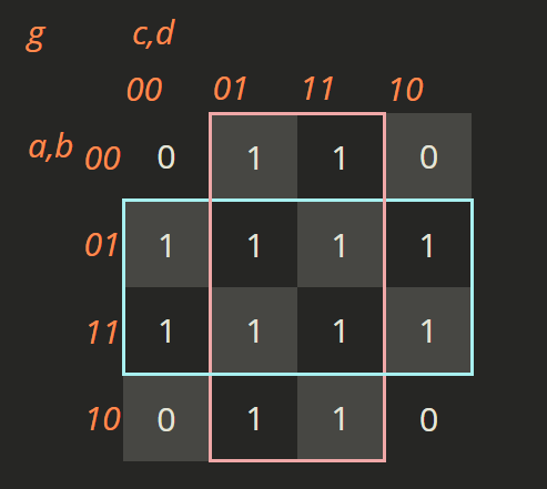
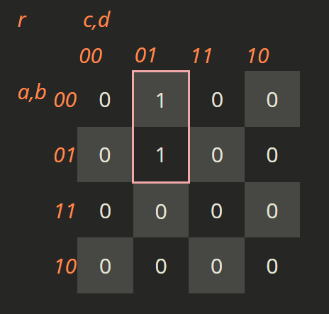
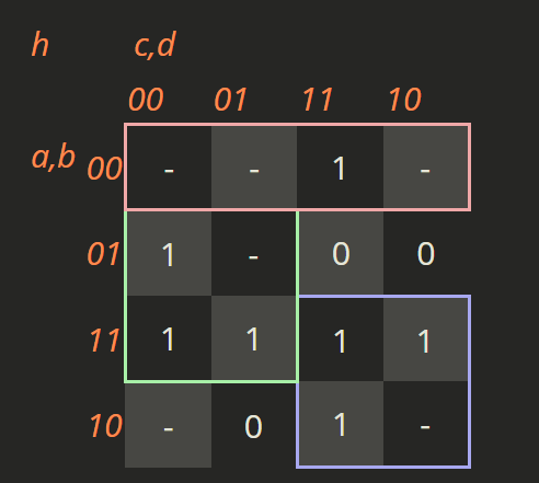
(d) Assume logic functions g=b+d and r=aˉ⋅cˉ⋅d. Among all the logic functions of h that satisfy
f=(g⋅h)+r,
derive a minimum sum-of-products expression of a logic function that has the minimum number of product terms with the minimum number of literals in its minimum sum-of-products form.
(2)
We design a sequential circuit with a 1-bit input u and a 3-bit output (q2,q1,q0) using three D flip-flops. The outputs of the D flip-flops are q2,q1, and q0, and they are the outputs of the sequential circuit as they are. When u=1, this circuit operates as a binary down counter whose cycle is 8. Namely, (q2,q1,q0) change like
(1,1,1)→(1,1,0)→(1,0,1)→⋯→(0,0,1)→(0,0,0)→(1,1,1).
When u=0, the circuit operates as a shift register, where q0 moves to q2, q2 to q1, and q1 to q0. For example, (q2,q1,q0) change like
(1,0,0)→(0,1,0)→(0,0,1)→(1,0,0).
Answer the following questions.
(a) Derive a state transition table.
(b) Let d2,d1, and d0 be the D input of the D flip-flops that output q2,q1, and q0, respectively. We derive d2,d1, and d0 as logic functions of q2,q1,q0, and u. Show the minimum sum-of-products expressions of d2,d1, and d0.
题目描述
回答全部问题。上划线、⋅、+ 分别表示逻辑非、与、或。
-
对逻辑函数
f=(a+b+c+d)(aˉ+b+cˉ+d)(aˉ+b+c)(a+bˉ+cˉ)(a+cˉ+d)
回答:
- 给出 f 的所有最简与或式。
- 给出 f 的所有最简或与式。
- 仅用三输入 NOR 门实现 f,使门数最少;可直接使用 a,b,c,d 及其反变量。
- 设 g=b+d、r=aˉcˉd。在所有满足
f=(g⋅h)+r
的 h 中,求一种最简与或式,使其乘积项数最少,并在此基础上文字数最少。
-
用三个 D 触发器设计输入 u、输出 (q2,q1,q0) 的时序电路,三个 Q 输出即为电路输出。
回答:
- 写出状态转移表。
- 令 d2,d1,d0 分别为输出 q2,q1,q0 的 D 触发器输入。求它们作为
q2,q1,q0,u 的逻辑函数的最简与或式。
Kai
(1)
(a)
Derive the K-map of fˉ and f:
| | |
|---|
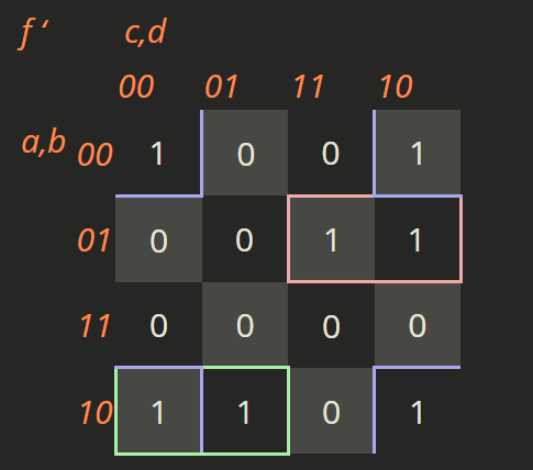 | 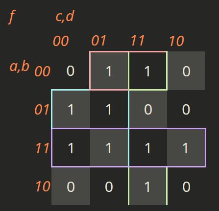 |
| fˉ=bˉdˉ+aˉbc+abˉcˉ | f=bcˉ+ab+aˉbˉd+bˉcd |
All minimum SOP expressions are
fff=bcˉ+ab+aˉbˉd+bˉcd,=bcˉ+ab+aˉbˉd+acd,=bcˉ+ab+aˉcˉd+bˉcd.
(b)
Simplified POS expression for f:
f=(b+d)(a+bˉ+cˉ)(aˉ+b+c)
(c)
From part (b), the minimum POS form is
f=(b+d)(a+bˉ+cˉ)(aˉ+b+c)
Using a two-level NOR–NOR implementation, let
x1=b+d=NOR(b,d,d)
x2=a+bˉ+cˉ=NOR(a,bˉ,cˉ)
x3=aˉ+b+c=NOR(aˉ,b,c)
Then the output is
f=x1+x2+x3=NOR(x1,x2,x3)
Therefore, the logic circuit is realized by four 3-input NOR gates only.
For the lower bound, apply De Morgan duality: F(a,b,c,d)=f(aˉ,bˉ,cˉ,dˉ) turns every NOR into a NAND with the same gate count. Its 1-inputs 1111,1001,0110 cannot be covered pairwise by one implicant, so F requires at least three product terms. To justify minimality, note that no literal is true on every 1-input and no entire literal half-space has output 1. The last NAND for F therefore cannot receive a primary literal. With at most three gates, its inputs must come from the preceding one or two gates. Parallel preceding gates give at most two product terms. If the first gate is T and the second is TP, feeding both into the last gate gives T+P, again at most two terms. Feeding only the second gives TP: nonconstant P forces a common literal on all 1-inputs, while constant P gives the complement of one product, contrary to the half-space property. Thus three gates cannot suffice.
(d)
Derive the corresponding K-map:
Expression for h:
h=aˉbˉ+bcˉ+ac
(2)
Since D flip-flops are used, the D inputs are exactly the next-state bits:
d2=q2+,d1=q1+,d0=q0+
The state behavior is:
- When (u=1): 3-bit binary down counter
- When (u=0): circular shift register
(q2,q1,q0)→(q0,q2,q1)
(a) State transition table
| Present state (q2q1q0) | u=0 next state | u=1 next state |
|---|
| 000 | 000 | 111 |
| 001 | 100 | 000 |
| 010 | 001 | 001 |
| 011 | 101 | 010 |
| 100 | 010 | 011 |
| 101 | 110 | 100 |
| 110 | 011 | 101 |
| 111 | 111 | 110 |
So we obtain the truth table for (d2,d1,d0).
(b)
K-map for d2
1-cells:
d2=Σm(1,2,6,10,11,13,14,15)
Rows: q2q1=00,01,11,10
Columns: q0u=00,01,11,10
| q2q1\q0u | 00 | 01 | 11 | 10 |
|---|
| 00 | 0 | 1 | 0 | 1 |
| 01 | 0 | 0 | 0 | 1 |
| 11 | 0 | 1 | 1 | 1 |
| 10 | 0 | 0 | 1 | 1 |
Grouping results:
- column 10 →q0uˉ
- block (11,10)×(11,10)→q2q0
- pair on row 11, columns 01,11 →q2q1u
- single cell (00,01)→qˉ2qˉ1qˉ0u
d2=q0uˉ+q2q0+q2q1u+qˉ2qˉ1qˉ0u
K-map for d1
1-cells:
d1=Σm(1,7,8,9,10,12,14,15)
Rows: q2q1=00,01,11,10
Columns: q0u=00,01,11,10
| q2q1\q0u | 00 | 01 | 11 | 10 |
|---|
| 00 | 0 | 1 | 0 | 0 |
| 01 | 0 | 0 | 1 | 0 |
| 11 | 1 | 0 | 1 | 1 |
| 10 | 1 | 1 | 0 | 1 |
Grouping results:
- block (11,10)×(00,10)→q2uˉ
- pair in column 01, rows 00,10→qˉ1qˉ0u
- pair in column 11, rows 01,11→q1q0u
d1=q2uˉ+qˉ1qˉ0u+q1q0u
K-map for d0
1-cells:
d0=Σm(1,4,5,6,9,12,13,14)
Rows: q2q1=00,01,11,10
Columns: q0u=00,01,11,10
| q2q1\q0u | 00 | 01 | 11 | 10 |
|---|
| 00 | 0 | 1 | 0 | 0 |
| 01 | 1 | 1 | 0 | 1 |
| 11 | 1 | 1 | 0 | 1 |
| 10 | 0 | 1 | 0 | 0 |
Grouping results:
- column 01→qˉ0u
- block (01,11)×(00,10)→q1uˉ
d0=qˉ0u+q1uˉ