京都大学 情報学研究科 通信情報システム専攻 2020年8月実施 専門基礎B [B-4]
Author
Description
Answer all the following questions.
(1)
Suppose that we design a circuit that compares two 2-digit binary integers and represented by two 2-bit inputs and . It outputs 1 in the case of , and outputs in the case of . Answer the following questions.
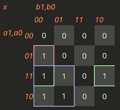
- (a) Give a minimal sum-of-products expression of output .
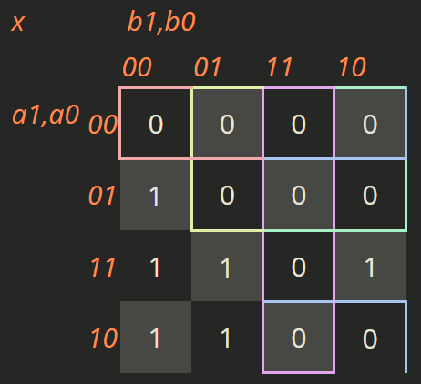
- (b) Give a minimal product-of-sums expression of output .
- (c) Derive a logic circuit that realizes with the minimum number of 3-input NAND gates only. Assume and their complements together with logic values and are available as inputs.
(2)
Suppose that we design a Mealy-type synchronous sequential circuit that has a 1-bit input and a 1-bit output . The circuit outputs when the value of the current input is different from the value at one clock earlier. It outputs when the value of the current input is the same as the value at one clock earlier. At the time the circuit starts operating, it is assumed that the value of the input at one clock earlier is . For example, when 010110 is fed to the circuit, it produces 011101. Answer the following questions.
- (a) Derive a state transition diagram of the circuit.
- (b) Show the state transition table and the output table with the minimum number of states. Explain how you verified that the number of states is minimal.
- (c) We would like to implement the circuit with the minimum number of D flip-flops. Derive the excitation function(s) of D flip-flop(s) in a minimal sum-of-products form. Here, the initial value of a D flip-flop is , and logic variables of the input and the output of a D flip-flop are and , respectively. If multiple flip-flops are used, distinguish them by subscripts.
- (d) Derive the output in a minimal sum-of-products form.
(3)
Suppose that we design a Mealy-type synchronous sequential circuit that restores the input from the output of the sequential circuit in Question (2). Answer the following questions.
- (a) Derive a state transition diagram of the circuit.
- (b) Show the state transition table and the output table with the minimum number of states. Explain the state transition and the output sequence for the input sequence of 011101.
Kai
(1)
(a)
Derive the corresponding K-map:
(b)
(c)

(2)
(a)
State definition:
- S0: the previous input was 0
- S1: the previous input was 1
Initial state: S0
State transition diagram:

(b)
| Input x | Current state | Next state | Output y |
|---|---|---|---|
| 0 | S0 | S0 | 0 |
| 1 | S0 | S1 | 1 |
| 0 | S1 | S0 | 1 |
| 1 | S1 | S1 | 0 |
Minimum-state verification: For the same input, the outputs in S0 and S1 are different (for example, when x=0, the outputs are 0 and 1, respectively). Hence the two states are distinguishable and cannot be merged. Therefore, the number of states is minimal (2 states).
(c)
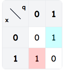
K-map for :

Minimal sum-of-products:
(d)
K-map for :
(Equivalently, .)
(3)
(a)
State definition:
- S0': the previous value of x was 0
- S1': the previous value of x was 1
Initial state: S0'
Input: Output:
State transition diagram:

(b)
| Input y | Current state | Next state | Output x |
|---|---|---|---|
| 0 | S0' | S0' | 0 |
| 1 | S0' | S1' | 1 |
| 0 | S1' | S1' | 1 |
| 1 | S1' | S0' | 0 |
Minimum-state verification: For the same input, the outputs in S0' and S1' are different (for example, when y=0, the outputs are 0 and 1, respectively). Hence the two states are distinguishable and cannot be merged. Therefore, the number of states is minimal (2 states).
(c)
Initial state: S0'
| Input y | Current state | Next state | Output x |
|---|---|---|---|
| 0 | S0' | S0' | 0 |
| 1 | S0' | S1' | 1 |
| 1 | S1' | S0' | 0 |
| 1 | S0' | S1' | 1 |
| 0 | S1' | S1' | 1 |
| 1 | S1' | S0' | 0 |
Output sequence: